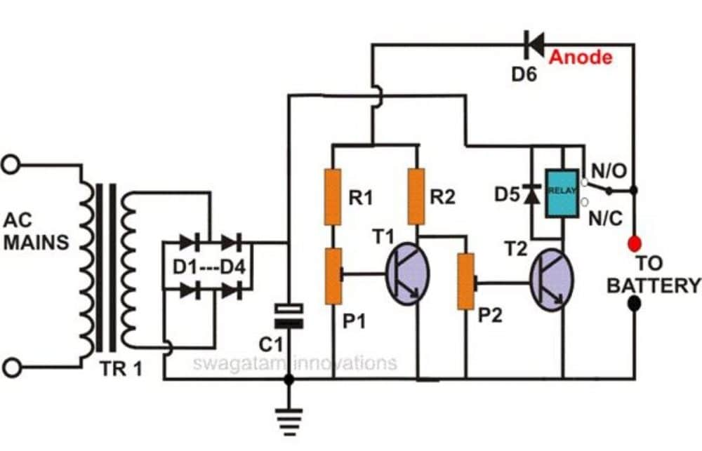
Battery Charger Circuit Diagram Headcontrolsystem
9 Simple Solar Battery Charger Circuits Last Updated on January 2, 2024 by Swagatam 430 Comments Simple solar charger are small devices which allow you to charge a battery quickly and cheaply, through solar energy. A simple solar charger must have 3 basic features built-in: It should be low cost. Layman friendly, and easy to build.
Electronic Circuits, Transformerless Power Supply, LED Drivers, Battery chargers, Solar Circuits
Battery Monitor Circuit Here is a battery monitor circuit which can be used to monitor the voltage of 12V lead acid batteries such as car batteries. The circuit is built around the LM3914 IC. USB Car Charger This is a project of a mini USB car charger circuit. The circuit can charge USB devices with car battery.
Car Alarm Circuit Wiring Diagram Ecu Pinout Obd1 Obd Truques Ksiazka Immobilizer Hks Spec Gol
How it works Battery charger with solar cells consists of three parts are… 1. The solar cell panels are used to change sunlight energy to electrical energy into direct current. Normally we would put solar panels are connected to each other. Until the voltage level as needed.
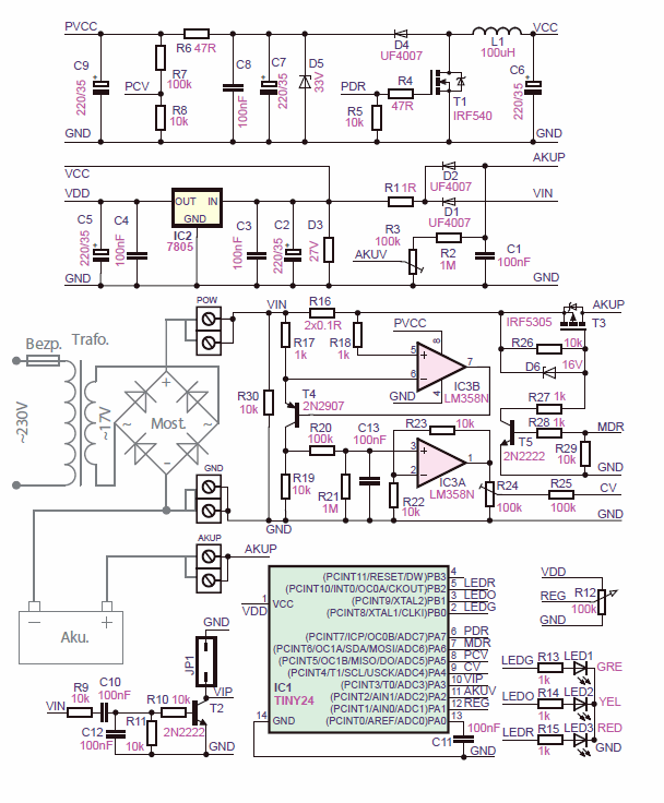
BATTERY CHARGER CIRCUIT DIAGRAM ATMega32 AVR
You can charge the batteries from 2-8 pcs, depending on an input voltage. In the circuit has two LED indicators. First LED, show charging status, when the battery is full, it will be off. Second LED, connect the battery correctly. The input voltage can use the power supply of 12V, 2A. At the charged current up to 800mA.

Wiring Diagram For Boat Battery Charger Circuit Diagram
Energizer - Rechargeable AA and AAA Battery Charger (Recharge Pro) with 4 AA NiMH Rechargeable Batteries Energizer - Rechargeable AA and AAA Battery Charger (Recharge Pro) with 4 AA NiMH Rechargeable Batteries . User rating, 4.7 out of 5 stars with 1613 reviews. (1,613) $28.49 Your price for this item is $28.49
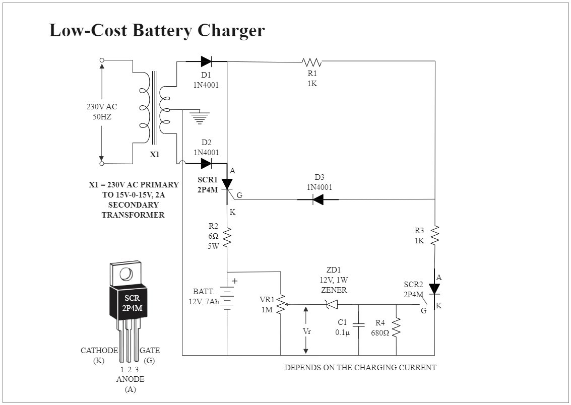
LowCost Battery Charger Circuit Diagram EdrawMax Template
This application note shows how to build an MCU controlled NiCd/NiMH universal battery charger with the cost-effective MCU MC68HC908QY4A, which is a member of the 8-bit family. The MC68HC908QY4A features are: High performance HC08 CPU core 5 V and 3 V operating voltage Up to 8 MHz internal bus operation at 5 V Trimmable internal oscillator

1A Generic Car Usb Charger Circuit Diagram
USB AAA Battery Charger Block Diagram Data (-) Data (+) Battery Voltage Feedback. PWM. PIC18F14K50. Board Temperature. Battery Select. Current Feedback Charge Regulator Circuit. MCP6V01 Circuit +5V. Battery Status LEDs ( Red) Slow blinking = Charging Fast blinking = Fault Solid ON = Fully Charged OFF = No Battery USB Status LED (Green)
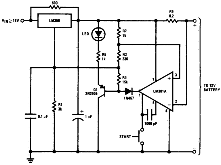
SelfRegulating Battery Charger Circuit
The circuit diagram shows an LM317 in constant-current configuration but without the usual fixed or variable resistor at the ADJ pin to determine the amount of output current. Also, there is no switch with an array of different resistors to select the charge currents for three cell or battery types we wish to charge: AAA, AA and PP3 (6F22).

Ac Circuit, Circuit Board, Battery Charger Circuit, Toroidal Transformer, Diy Amplifier
The NiMH Battery Charger Circuit comes with numerous features. Here's a list of the main ones: A complete fast charger controller for single, two series to 4 series cell NiMH batteries. Automatic recharge to keep these rechargeable batteries charged. Accurate charge current. Manual shutdown.

3V Battery Charger Circuit Diagram
Our integrated circuits and reference designs help you create a battery charger that is efficient and provides various forms of quick charging for AA and AAA batteries. Design requirements. Consumer battery charger systems often require: Highly-efficient and low-standby power management. Fast and efficient battery management.

Simple Battery Charger Wiring Diagram Anya Circuit
Specifications This charger has the following specifications: Size: 3.8″L x 1.2″W x 0.7″H (9.7cm x 3.0cm x 1.5cm). Cells: Two AA, NiMH or NiCd Charging Current: 470mA Charge Termination Method: Battery Temperature (33°C) Trickle Current: 10mA Power Source: Desktop, Laptop, or Hub USB port Operating Conditions: 15°C to 25°C (59°F to 77°F)

Repair Bauer Battery Charger Circuit Diagram Elle Circuit
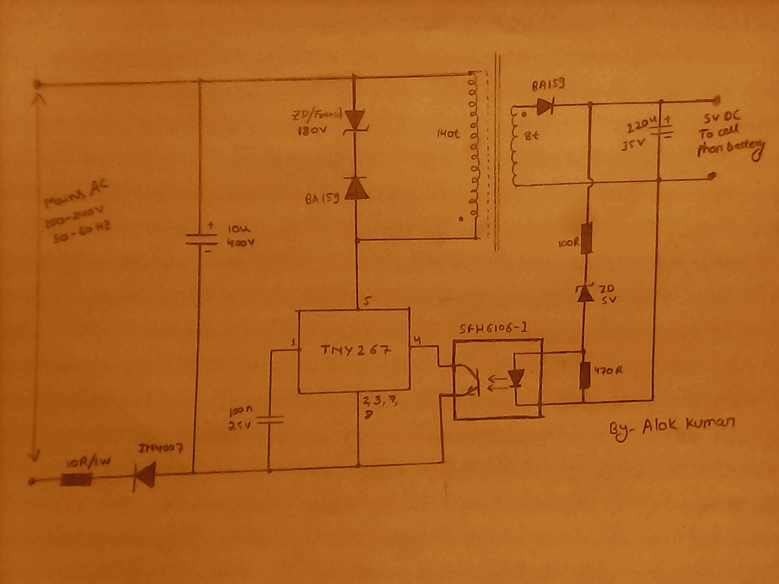
You can charge your mobile phone battery using AA batteries. The final circuit is very small so that it can work as an emergency portable battery charger. Almost all USB powered devices (that can be charged via USB cable) like mobile phones, iPod, MP3 players, cameras etc. can be charged.

Charger Circuit Diagram Wiring Scan
3 Working Explanation This practically consequential solar charger circuit utilizes to charge a pair of AA or AAA rechargeable battery cells from solar light. Moreover, the circuit utilizes to charge some other electronic devices as well to run perpetually.

nickel cadmium battery charger circuit diagram Circuit Diagram
A Guide to Building Battery Chargers Posted by Graham Lambert | DIY Electronics | 2 In this tutorial, we will take a look at charging circuits for sealed lead acid (SLA), Nickel Cadmium (NiCd), Nickel Metal Hydride (NiMH), and Lithium Polymer (LiPo) batteries. We will provide schematics and instructions on how to build them.

Adapter Circuit Diagram » Wiring Core
There are three fundamental parameters that need to be considered while charging the battery safely: Constant Current (CC) Constant Voltage (CV) and Auto Cut-off Constant Current: Here, the amount of battery charging current is fixed. This current is maintained by varying the voltage.
Alkaline Battery Charger using BC337 Transistors
Circuit Diagram How it Works The simple configuration detailed here is designed to charge a single 500 mAh 'AA' cell with the recommended charge rate of close to 50 mA, nonetheless it could conveniently be customized cheaply to charge several cells together by repeating the area shown in dotted lines.